Some experiments with double balanced mixers and GNURadio
Hi all,
This post is all about frequency mixing , specifically double balanced mixers using diodes or ring mixers , commonly used in communication circuits . The circuit diagram of a ring mixer is given below .
(Courtesy : Radio-electronics )
Now let us turn out attention to the GNURadio flowgraph that is used .The graph is given below.


The next fun is with the GNURadio plots . Remember the FFT plots in the flowgraph ? Here are the plots . You can see two spikes in the output . Only one is the true one . The other one appears because I don't use quadrature sampling as an image . Neglect it .


This post is all about frequency mixing , specifically double balanced mixers using diodes or ring mixers , commonly used in communication circuits . The circuit diagram of a ring mixer is given below .
(Courtesy : Radio-electronics )
 |
| Schematic of a double balanced mixer. |
As you can see , this makes use of two transformers and a four diodes . For most of the HF work , switching diodes like 1N4148 suffice . However , for better performance Schottky diodes like 1N5711 can be made use of . For more information on the working of this mixer and construction aspects , I strongly recommend the excellent video by W2AEW on ring mixers given below .
So what I wish to explain in this video is a set of experiments carried out using a double balanced mixer which I shall call DB mixer for convenience :) The test gear consists of a DDS VFO , a crystal Colpitts oscillator , a variable power supply , CRO , RTL-SDR and the PC sound card . The software tools used are GQRX and GNURadio . Needless to say , the software run in Linux environment ( I use Linux Mint in my shack now ) .
A block diagram of the entire experiment is given below .
 |
| Block Diagram |
The two RF signals are derived from the DDS VFO and a crystal oscillator . In this , we use a 27.000 MHz crystal from KDS . It is built into a Colpitts oscillator and an emitter follower is used to buffer the signal . It is then fed into the RF port of the mixer . The IF port is fed from the DDS with a 0.1 uF capacitor used to block the DC . No buffer or attenuator is used here , however using an attenuator is a good way to keep the VFO happy under a large variety of loads . The output from the mixer is given to various equipment as given above . However , the CRO and RTL-SDR are used alternatively as I use only a single BNC connection from the mixer . A connection from the mixer output goes to the line-in port ( the blue port ) of my PC soundcard . My PC is an old one ( 8+ years ), therefore it has a line-in port ! The connection is a direct one using shielded cable and only a potentiometer is used to reduce the signal level into the audio port . I know that this has the potential to raise eye brows as I have paid least attention to impedance matching and using proper cables . Let me once again emphasize that this is just a simple experiment and all that I'm interested is frequencies . The close-up shot of the circuit is given below .
 |
| The mixer and oscillator circuits . |

The flowgraph is a simple and straightforward one . The input source is taken as an audio source block . The input is chosen as line-in the Linux audio settings . The number of inputs is set to two , for stereo input , even though I use only one channel . The float output of this block is converted into complex form using a float to complex block . The output of this block is then given to a low-pass filter with decimation . The decimation is set as a variable to change the decimation . Why ? Because if I need to observe a phenomena which has frequency change of the order of a few hertz , I change set the set the cut off frequency low , use high decimation and apply FFT on it . If the phenomena that I need to observe is a one with frequency changes of the order of a few kHz , I can set the cut-off frequency much higher , apply low decimation and use a similar FFT on the phenomena . If I needed to observe a few Hz case with higher number of samples , I may need to use a high point FFT and this can cause much load on the CPU and can clog the display . The result appears great with the current setup . The output from the LPF is given to a FFT sink as well as a Waterfall sink . The waterfall sink is disabled in the above flowgraph .
Now let us start the real experiment. In the first experiment , we will use only the CRO and line-in port . The VFO frequency is set around 27 MHz , to be precise 27.011380 MHz in our case . Let me remind you that the VFO is not a calibrated one . Even though it has a precision of 1Hz , it is not accurate . That said , the frequency is close to the frequency of oscillation of the oscillator that we are using .

So what will you obtain at the output ? The sum and difference , of course with a sea of harmonics ! The sum is around 54 Mhz and we are not currently interested in it . The real fun lies in the difference signal , which is now set to below 100 Hz by tweaking the VFO frequency . A word of caution , the frequency of this signal can change rapidly due to power supply variations as well as stray capacitance and other nasty reasons . Therefore I won't say that it is precisely so and so . Only a rough value can be given now :D .
Now let us turn our attention to the output seen on the CRO . The timebase is set to a few ms (5 ms to 100 ms) , which can be changed as you wish :P . As can be seen now , the output has many components , the low frequency variation can be seen clearly in the two pictures below . Now why do you see only a portion of the waveform ? It is due to the exposure time of the camera that I use .


In the following plot , the frequency has changed as I changed the VFO output by a few Hz ( roughly 10Hz ) . The change in the spectrum can be seen clearly . It is for this utility that decimation is done in the LPF section .

The next display is with the FFT as well as waterfall plots in the same window . This is by enabling the waterfall block in the flowgraph . Long term frequency variations can be seen in waterfall plots . However , this can have a lot of sources , including drift in the Xtal oscillator , drift in VFO , and clock variations in the soundcard .

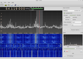
So far we were dealing with the two inputs being very close in frequency . Let us now use two frequencies which are not close in frequency . In this experiment we will shift our focus to the RTL-SDR output . So I disconnect CRO as well connection to the line in and connect the BNC to the SDR input . Now let us tune the VFO to some frequency .

As you can see,the frequency chosen is not a multiple of 27 MHz . Why ? If I choose a multiple , I won't be able to say precisely whether the 54 MHz that I see is a harmonic or the actual sum of the frequencies . Choosing two frequencies that have no such connection gets rid of that ambiguity . So , I set the frequency to 30.111180 MHz . If you see relics of the previous frequency , you are right ! I was too lazy to change the value of other positions :D . So what will you see in the output ? As said earlier , I'm interested in the sum , which is around 57 MHz . Now that is what you see in the GQRX window below ! The sum frequency is very strong , riding very high above the noise floor .

The ring modulator claims to get rid of the carrier and modulating signals in the output . A quick check showed me the same .

Stay tuned for more updates on GNUradio + RTLSDR experiments !
73s
DE VU3VWB

Hi,
ReplyDeletei've a older yaesu ft 7b .
I've changed the diode with bat85s .
the noise it's decreased but the radio don't trasmit (the mixer it's the same on tx and rx)
Why?