Thursday, May 21, 2020

Bias tee modification of HiLetgo RF amplifiers

Hi folks,

There are some inexpensive RF amplifiers available in the hobby market by various names. They may be called LNAs, if you consider 3 dB noise figure as low noise. I purchased two of them from Amazon from a seller called HiLetgo. However documentation is sparse and the design is not all that great. People have had frustrating experiences with this type of LNA. Information regarding power supply to this board is practically non-existent, with voltage suggestions ranging from 5V to 12V ! Some even obtained the "magic smoke". Nonetheless they are reasonably cheap and therefore modifications can be done to make them useful. Let us now take a closer look at the board.

Figure 1. The amplifier without any modification.

Fig.1 shows the board without any modification. There are two SMA connectors and provision to externally power the board. The active element is an MMIC, with N02 as the marking. Other users have identified the MMIC as INA-02184 from HP. It seems to match what I have, so the datasheet is linked here . I highly recommend that you browse the datasheet before reading further. The published values for some device parameters (at 500 MHz for RF specs) are

  1. ~2 dB noise figure 
  2. ~31 dB gain
  3. ~ 800 MHz of 3dB bandwidth
  4. Typical device voltage ~ 5.5V, maximum 7V
Now it is clear that the device should not be fed with more than 7V, unless you want to generate magic smoke. But 9V to 12V seems to work for many users, how is that possible ? The devil is in the details. If you take a closer look at the board, the DC goes through a bias tee like arrangement to pin-3. There is a 180 ohm smd resistor in series. The Id vs Vd curve in the datasheet gives something like 35mA of current for 5V. If you solve for the series resistance to use 12V, you get about 200 ohms. So that explains the results that others get ! However, the tiny resistor is forced to dissipate something like 0.2W of power. I don't wish to put stress the resistor, or even use batteries to power this device. 

I will be using this LNA with RTL-SDR blog v3 dongle almost exclusively. Therefore my intention is to use the bias tee feature in the SDR to power this board. The maximum current that this SDR can provide is 150mA; the LNA consumes only about 30mA and therefore the SDR will not be damaged. This will simplify my signal chain since the LNA now can be placed closer to the antenna and no separate powering arrangement has to be made. 

It turns out that it is easy to do this modification, since the MMIC is designed to be fed with DC through its pin-3. This involves two steps
  1. Remove the blocking capacitor and form a solder bridge across the pads.
  2. Remove the SMD component connecting the DC line to pin-3. I assume this is some sort of RF choke, expert comments welcome !
Figure 2. The amplifier after modification.
Notice the absence of the yellow SMD component (RF choke ?) and output coupling capacitor.

Fig.2 shows the LNA board after modification. The results look promising. I can now feed power to the LNA from RTL-SDR, with no problem whatsoever. I am yet to do a proper measurement of gain and other parameters, but it definitely works. Fig.3 shows the unmodified and modified LNAs side by side for comparison.

Figure 3. Left one is without any modification, right one has been modified for bias tee operation.

Would I recommend this to someone else ? Yes, provided you know why an LNA is needed and the caveats associated with using one in your system. 

Jishnu,
VK6JN/VU3VWB

Wednesday, January 17, 2018

Digital modes with VUSDR and Quisk

Hello all,

VUSDR is a popular TxRx SDR in India. Inspired by Peaberry SDR, it can also be used in Linux machines with Quisk as the software. In this post, I won't go into the details of configuring Quisk for normal SDR. Instead, assuming that it is already done, I shall go into the details of configuring it for digital modes especially configuring for WSJT-X for Ubuntu 16.04. As for normal Quisk configuration, I might blog about it in future.
A word of caution ! These steps worked for me, but I cannot guarantee that they will work for you.

So let's get started !
First download and install WSJTX from the following link.

https://physics.princeton.edu/pulsar/k1jt/wsjtx.html

You can double click and install the .deb file or can use terminal to install. I used the following command to install it (remember to open a terminal and navigate to the folder where the .deb file is present before typing this command)

sudo apt install ./wsjtx_1.8.0_amd64.deb

Next step is to install PulseAudio volume control. For that, type the following following in the terminal.

sudo apt install pavucontrol

Now we need to configure two virtual audio cables to route audio from Quisk to WSJT-X and back. For that, open a terminal and type the following.

cd /etc/pulse/
sudo gedit default.pa

In the file that opens, enter the following lines and save it. I use gedit as it is convenient for people with null expertise. Experts can use vim or some other editor !

#Virtual Cables
load-module module-null-sink sink_name=vac1 sink_properties=device.description=VCable1
load-module module-null-sink sink_name=vac2 sink_properties=device.description=VCable2

At this point, it is good to restart your machine. Now if you run Quisk, you will see new audio sources and sinks VAC1 and VAC2 added as shown in below screenshots. These shall be used for further  communications between Quisk and WSJT-X.


Next you need to inform your Quisk installation about using these new VACs as audio source and sink. For that edit your .quisk_conf.py and change the lines as shown below. It is good to comment the existing settings instead of deleting them so that you can revert back if needed. The changes are as follows - check line numbers 12 and 26 in the screenshot.

name_of_sound_play = "pulse:vac1"
microphone_name = "pulse:vac2" 


Basically what this does is to set audio source as VAC2 and sink as VAC1. Now to need to set this source and sink for WSJT-X. For this edit your WSJT-X audio settings as shown below. Set input to vac1.monitor and sink to vac2. Also set power high so as to trigger the VOX in quisk.
Next set VOX in quisk to ON and set the level to minimum so that it can be triggered easily. 


Done ! You have now configured Quisk for WSJTX ! See what I found on 40m around 7074 kHz :) So far I didn't have success with TX due my antenna inefficiencies. 
Also, I may edit this blog in future when I make changes :) 


Until next time,
73 DE VU3VWB

Tuesday, May 23, 2017

Using FTDI USB to serial converter in Linux - Ubuntu

I recently purchased an FTDI USB to serial converter - FT232RL. However I could not use it properly in Windows. With some googling, I could find a way to use it under linux. Following are the steps to be used in Ubuntu to get it working.

Open a terminal and type the following commands.

sudo modprobe ftdi_sio
sudo chmod 666 /sys/bus/usb-serial/drivers/ftdi_sio/new_id
nano /sys/bus/usb-serial/drivers/ftdi_sio/new_id

In the file that got opened, type 0403 8a8a and save it. The number can be found by typing lsusb in another terminal.
Now unplug and re-plug the module. Type 

ls /dev

and you should see /ttyUSB0 in the list. Now use some serial terminal (like screen) to view the data !
For opening a screen session, the following command is used. Here 115200 is the baud rate.

sudo screen /dev/ttyUSB0 115200

Thursday, January 14, 2016

A simple guide to installing and using RTL-SDR and related software in Ubuntu

Hello all !
In this post , let me help you install and use RTL-SDR and related software in Linux , specifically Ubuntu . The software being installed are  GNUradio and GQRX .

GQRX
I have tried this procedure in several systems running Ubuntu 14.04 LTS as well as Mint OS ( which is based on Ubuntu ) . The procedure assumes that you have access to root password and knows basics of Linux terminal. Moreover you need a working internet connection. If you don't know how to use the terminal , then please watch some youtube videos on the same . So let's start !

Step 0

Install Ubuntu ! This is the right decision that you can make . Linux is ideal for developers and hackers ( I mean hackers like Richard Stallman and not crackers ) .

Step 1

Open a linux terminal ( Ctrl+Alt+T) and type the following command

sudo apt-get update

You will be prompted for the password . Give it . It won't be shown on the screen .
This will update your Ubuntu installation and install the latest updates . You may need to wait for a few minutes to half an hour depending on your internet speed and how long your system remained stale ( without any update ).
Don't close the terminal , we need it ! If you close , don't worry . You just need to provide the root password when you open a new terminal and execute the following commands .

Step 2

After updating , install GQRX .The command is given below .

sudo apt-get install gqrx-sdr

This will give you a GUI interface for RTL-SDR as well installs the GNUradio packages for you , which is essential for developing some useful radio flowgraphs employing DSP . You can install GNUradio independently , if you wish .

Step 3

Now that you have GQRX , install the rtlsdr tools . The command is

sudo apt-get install rtl-sdr

This should be pretty easy !

Step 4

Now connect the RTL-SDR and run the following command

lsusb

The sdr should be listed as a Realtek device . So far so good . Now we need to blacklist the device so that the kernel modules for DVB won't load when you plug it . So , execute the following commands on the terminal .

sudo rmmod dvb_usb_rtl28xxu

After this , we need to create a file that blacklists the dongle so that the modules won't load in future . Execute the commands .

sudo su
echo blacklist dvb_usb_rtl28xxu > /etc/modprobe.d/rtlsdr.conf
exit


These commands have been taken from the website : RTLSDR Scanner Installation

Step 5
If you have been able to perform the above operations without any glitch , you are done ! Unplug and reconnect the dongle . Now open a terminal and type

gqrx

Now the GQRX screen will pop up . You can run the GQRX , change the settings etc .
If you want to get the GRC or GNUradio companion , type the following command.

gnuradio-companion

This will give you the GRC window . Please note that you won't be able to use the SDR simultaneously from both GQRX and GRC .

I hope that this tiny write-up will help you in installing the SDR ! Feel free to contact me in case some questions arises in your mind.

Greetings and 73s , this is VU3VWB   

Monday, December 28, 2015

Some experiments with double balanced mixers and GNURadio

Hi all,
This post is all about frequency mixing , specifically double balanced mixers using diodes or ring mixers , commonly used in communication circuits . The circuit diagram of a ring mixer is given below .
(Courtesy : Radio-electronics )
Schematic of a double balanced mixer. 
As you can see , this makes use of two transformers and a four diodes . For most of the HF work , switching diodes like 1N4148 suffice . However , for better performance Schottky diodes like 1N5711 can be made use of . For more information on the working of this mixer and construction aspects , I strongly recommend the excellent video by W2AEW on ring mixers given below . 


So what I wish to explain in this video is a set of experiments carried out using a double balanced mixer which I shall call DB mixer for convenience :) The test gear consists of a DDS VFO , a crystal Colpitts oscillator , a variable  power supply , CRO , RTL-SDR and the PC sound card . The software tools used are GQRX and GNURadio . Needless to say , the software run in Linux environment ( I use Linux Mint in my shack now ) .
A block diagram of the entire experiment is given below . 
Block Diagram 
The two RF signals are derived from the DDS VFO and a crystal oscillator . In this , we use a 27.000 MHz crystal from KDS . It is built into a Colpitts oscillator and an emitter follower is used to buffer the signal . It is then fed into the RF port of the mixer . The IF port is fed from the DDS with a 0.1 uF capacitor used to block the DC . No buffer or attenuator is used here , however using an attenuator is a good way to keep the VFO happy under a large variety of loads . The output from the mixer is given to various equipment as given above . However , the CRO and RTL-SDR are used alternatively as I use only a single BNC connection from the mixer . A connection from the mixer output goes to the line-in port ( the blue port ) of my PC soundcard . My PC is an old one ( 8+ years ), therefore it has a line-in port ! The connection is a direct one using shielded cable and only a potentiometer is used to reduce the signal level into the audio port . I know that this has the potential to raise eye brows as I have paid least attention to impedance matching and using proper cables . Let me once again emphasize that this is just a simple experiment and all that I'm interested is frequencies . The close-up shot of the circuit is given below .

The mixer and oscillator circuits 
Now let us turn out attention to the GNURadio  flowgraph that is used .The graph is given below.


The flowgraph is a simple and straightforward one . The input source is taken as an audio source block . The input is chosen as line-in the Linux audio settings . The number of inputs is set to two , for stereo input , even though I use only one channel . The float output of this block is converted into complex form using a float to complex block . The output of this block is then given to a low-pass filter with decimation . The decimation is set as a variable to change the decimation . Why ? Because if I need to observe a phenomena which has frequency change of the order of a few hertz , I change set the set the cut off frequency low , use high decimation and apply FFT on it . If the phenomena that I need to observe is a one with frequency changes of the order of a few kHz , I can set the cut-off frequency much higher , apply low decimation and use a similar FFT on the phenomena . If I needed to observe a few Hz case with higher number of samples , I may need to use a high point FFT and this can cause much load on the CPU and can clog the display . The result appears great with the current setup . The output from the LPF is given to a FFT sink as well as a Waterfall sink . The waterfall sink is disabled in the above flowgraph . 

Now let us start the real experiment. In the first experiment , we will use only the CRO and line-in port . The VFO frequency is set around 27 MHz , to be precise  27.011380 MHz in our case . Let me remind you that the VFO is not a calibrated one . Even though it has a precision of 1Hz , it is not accurate . That said , the frequency is close to the frequency of oscillation of the oscillator that we are using . 

So what will you obtain at the output ? The sum and difference , of course with a sea of harmonics  ! The sum is around 54 Mhz and we are not currently interested in it . The real fun lies in the difference signal , which is now set to below 100 Hz by tweaking the VFO frequency . A word of caution , the frequency of this signal can change rapidly due to power supply variations as well as stray capacitance and other nasty reasons . Therefore I won't say that it is precisely so and so . Only a rough value can be given now :D . 
Now let us turn our attention to the output seen on the CRO . The timebase is set to a few ms (5 ms to 100 ms) , which can be changed as you wish :P . As can be seen now , the output has many components , the low frequency variation can be seen clearly in the two pictures below . Now why do you see only a portion of the waveform ? It is due to the exposure time of the camera that I use . 


The next fun is with the GNURadio plots . Remember the FFT plots in the flowgraph ? Here are the plots . You can see two spikes in the output . Only one is the true one . The other one appears because I don't use quadrature sampling as an image . Neglect it .


In the following plot , the frequency has changed as I changed the VFO output by a few Hz ( roughly 10Hz )  . The change in the spectrum can be seen clearly . It is for this utility that decimation is done in the LPF section .


The next display is with the FFT as well as waterfall plots in the same window . This is by enabling the waterfall block in the flowgraph . Long term frequency variations can be seen in waterfall plots . However , this can have a lot of sources , including drift in the Xtal oscillator , drift in VFO , and clock variations in the soundcard . 


Monday, August 24, 2015

The trouble with double balanced mixers

Hello folks !
I never knew that overdriving double balanced mixers can actually reduce their very purpose of carrier suppression . I found this out while watching a video on microwave mixers . This problem was plaguing my Bitx40 , one of the reasons why I didn't put a linear stage on it and come on air . Instead of using its own LC VFO , I use a DDS VFO external to the Bitx40 . It had stupendous amount of carrier in its output . Trying to figure out the cause , I changed the diodes , rewound the transformers , but nothing worked out . However reducing the drive level alleviated the problem . After doing a few simulations of this in TINA-TI and obtaining the results , I did the same with the actual Bitx40 PCB . The CRO output looks much better now compared to the previous cases . The tests on a receiver too is encouraging as I can hear my sound as an SSB signal in it . Needless to say , the BFO stage has to be tuned to match the crystal filter's range to ensure best operation . If everything goes well , I will attach a IRF510 linear and come on air soon !

73s 

Sunday, July 19, 2015

Receiving NOAA weather images using RTL-SDR

HI all ,
In one of my previous posts , I explained how to receive ISS SSTV images (see RECEIVING SSTV FROM ISS ! Steps involved in decoding when using MMSSTV ).Today I will describe reception of APT images from NOAA series of satellites using RTL-SDR dongles . The steps are outlined below .

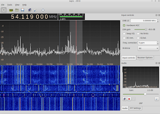
  1. Record the WBFM signals from one of the NOAA weather sats ( NOAA 15,18 or 19) . You can use any of the satellite prediction software like Orbitron,GPredict etc to do the predictions . The recording can be done using any the SDR software like SDRsharp , HDSDR or GQRX . I use GQRX as my lab PC is Linux powered (see Lab / Shack PC running Linux ! ) . The recording should be in .WAV format with the filter set tot the right bandwidth .
  2. Import the .WAV file into Audacity . Change the project rate to 11025 Hz and split the stereo track into two ( If u don't know audacity , this can be done by clicking the small arrow button near the tracks ) . Delete one of the tracks and make the other track mono .
  3. Export the file into .WAV format 
  4. Open APTdecoder which is a nice and simple software to decode APT images . Click the folder icon to open the OPEN dialogue box . Navigate to the folder where you have kept the new .WAV file and open it .
  5. You will now see the image appearing on the seen . Bravo ! You have done it !
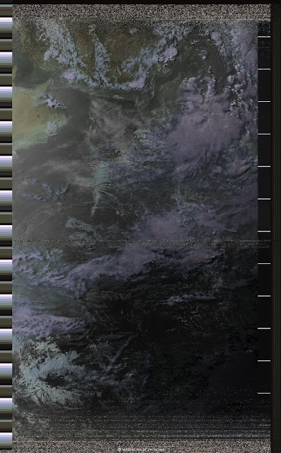
  6. Further , you can rotate the image , enhance it , equalize it , and create false color images by combining the A and B tracks .
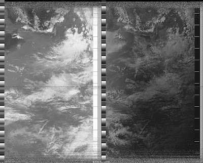
Here is an image that I decoded today (July 19 , 2015) evening at ~17.42 IST . The satellite was NOAA 18 with the antenna being a GP and cable RG-58 . It was a westerly pass and was the best , considering my antenna location .  It would be much better to use antennas like turnstile antenna .
A & B channels 

False colored image
73s !
DE VU3VWB